
C++, OpenGL and more...
 Megabyte Softworks Facebook
 Megabyte Softworks Patreon
Merry Christmas and I welcome you to my 9th tutorial of my OpenGL4 Tutorial Series! This one is a simpler one, we will only learn about how to render stuff in 2D using orthographic projection matrix and how to render 2D elements over the scene nicely (just like you have HUDs in games showing your hitpoints, ammo etc...). We will really briefly touch blending, although there will be a separate tutorial for it, but we can improve the quality of our 2D rendered elements using it. The last thing we will learn here is, what is fragment discard. Off to learning!
In orthographic projection, you simply take your object and you project it onto a drawing surface from one view (let's say from front) using lines that are perpendicular to the drawing surface. If you don't understand, let's just take a simple picture:
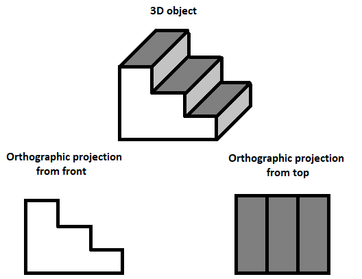
Can you see this now? We look from one direction and draw lines from every point of the object to the rendering surface and that's it! In our case, rendering surface is our 2D screen and we're looking at the objects from front. Moreover, orthographic projection will be even simpler, because we won't even project 3D objects, but only 2D objects. Our projection matrix will correspond to our window, so that if we render something at [100, 100], it will indeed appear on position [100px, 100px] in the window coordinates!
In class OpenGLWindow, I have created new variable called _orthoMatrix, which we recalculate everytime the window is resized. In order to calculate orthographic projection matrix, we will simply use glm function and provided window dimensions:
_orthoMatrix = glm::ortho(0.0f, float(width), 0.0f, float(height));
And that's it! We now have orthographic projection matrix, which we can use for 2D rendering! In this tutorial, I have decided to render Christmas tree in the bottom-left corner of the window and snowflake in the bottom-right corner of the window. This will be our HUD  ! In order to render it, we will have to prepare some things though. Let's go through the initialization code:
void OpenGLWindow::initializeScene()
{
    // ...

	ortho2DVertexShader.loadShaderFromFile("data/shaders/tut009/ortho2D.vert", GL_VERTEX_SHADER);
	ortho2DFragmentShader.loadShaderFromFile("data/shaders/tut009/ortho2D.frag", GL_FRAGMENT_SHADER);

    // ...

	ortho2DProgram.createProgram();
	ortho2DProgram.addShaderToProgram(ortho2DVertexShader);
	ortho2DProgram.addShaderToProgram(ortho2DFragmentShader);

    if (!ortho2DProgram.linkProgram())
	{
		closeWindow(true);
		return;
	}

    // ...

    hudSampler.create();
	hudSampler.bind();
	hudSampler.setMagnificationFilter(MAG_FILTER_BILINEAR);
	hudSampler.setMinificationFilter(MIN_FILTER_BILINEAR);

	glGenVertexArrays(1, &hudVAO); // Creates one Vertex Array Object
	glBindVertexArray(hudVAO);

	hudVerticesVBO.createVBO();
	hudVerticesVBO.bindVBO();
	hudVerticesVBO.addData(static_geometry::quad2D, sizeof(glm::vec2) * 4);

	hudVerticesVBO.uploadDataToGPU(GL_STATIC_DRAW);
	glEnableVertexAttribArray(0);
	glVertexAttribPointer(0, 2, GL_FLOAT, GL_FALSE, sizeof(glm::vec2), (void*)0);

	hudTexCoordsVBO.createVBO();
	hudTexCoordsVBO.bindVBO();
	hudTexCoordsVBO.addData(static_geometry::quad2D, sizeof(glm::vec2) * 4);

	hudTexCoordsVBO.uploadDataToGPU(GL_STATIC_DRAW);
	glEnableVertexAttribArray(1);
	glVertexAttribPointer(1, 2, GL_FLOAT, GL_FALSE, sizeof(glm::vec2), (void*)0);
}
As you can see, there is a new shader program especially for rendering 2D objects called ortho2DProgram. Furthermore I have created a separate sampler for 2D objects. The reason is, that we don't need mipmapping here, because for now I plan to display 2D object as big as it was originally. Even if I had to resize it, then there might be some performance penalty, but I really think that amount of rendered 2D stuff is neglibible in comparison to 3D stuff, so in the end, it doesn't even matter (hope you understood that Linkin Park reference ). And I have also created new static geometry consisting of glm::vec2 vertices, anchored in the lower-left vertex:
namespace static_geometry
{
    // ...

	// Render using triangle strip!
	glm::vec2 quad2D[4] =
	{
		glm::vec2(0, 1), // Top-left point
		glm::vec2(0, 0), // Bottom-left point
		glm::vec2(1, 1), // Top-right point
		glm::vec2(1, 0) // Bottom-right point
	};
}
One question might arise in your head though - why not center this, just as we did by the 3D cube? The reason is simple - it's easier to position objects in game HUD using lower left point rather than with center point. Another advantage now is, that these points are exactly same as texture coordinates, that we will use.
As mentioned, there is a dedicated shader program for rendering 2D objects, consisting of vertex and fragment shader. The following code snippet represents vertex shader:
#version 440 core

uniform struct
{
	mat4 projectionMatrix;
	mat4 modelMatrix;
} matrices;

layout(location = 0) in vec2 vertexPosition;
layout(location = 1) in vec2 vertexTexCoord;

smooth out vec2 ioVertexTexCoord;

void main()
{
	mat4 mvpMatrix = matrices.projectionMatrix * matrices.modelMatrix;
	gl_Position = mvpMatrix * vec4(vertexPosition, 0.0, 1.0);
	ioVertexTexCoord = vertexTexCoord;
}
It is actually very similar to the 3D rendering, one significant difference is, that we receive 2D vertices as position instead of 3D vertices. This means, that if we perform matrix multiplication, we have to extend our vec2 to vec4 using 0.0 for Z coordinate and 1.0 for W coordinate. We won't do anything with texture coordinate, just pass it further to the fragment shader  .
.
Fragment shader also deserves some explanation:
#version 440 core

layout(location = 0) out vec4 outputColor;

smooth in vec2 ioVertexTexCoord;

uniform sampler2D sampler;
uniform vec4 color;

void main()
{
	vec4 texel = texture(sampler, ioVertexTexCoord);
	if(texel.a == 0.0)
		discard;
	outputColor = texel*color;
}
There is not that much stuff going on, we just take the texel from texture and in the end, we output texel multiplied with uniform color. But there is one new thing we will learn today - fragment discarding.
Because our christmas tree and snowflake textures are PNG images with transparency, we can use this information to simply not render invisible points! It's those points, that have alpha component set to zero. So if there comes a pixel to fragment shader containing zero alpha, we will simply discard it, that means, it won't be rendered at all, like if it has never been there in the first place! This is super cool, because we can create 2D transparent objects this way .
Let's have a look at the rendering code in the renderScene() function:
void OpenGLWindow::renderScene()
{
	// ...

	glDisable(GL_DEPTH_TEST);

	if (blendingEnabled)
	{
		glEnable(GL_BLEND);
		glBlendFunc(GL_SRC_ALPHA, GL_ONE_MINUS_SRC_ALPHA);
	}
	glDepthMask(0);

	int width, height;
	glfwGetWindowSize(getWindow(), &width, &height);

	ortho2DProgram.useProgram();
	glBindVertexArray(hudVAO);
	hudSampler.bind();
	ortho2DProgram["matrices.projectionMatrix"] = getOrthoProjectionMatrix();
	ortho2DProgram["sampler"] = 0;
	ortho2DProgram["color"] = glm::vec4(1.0, 1.0, 1.0, 1.0);

	// Render Christmas tree bottom left
	glm::mat4 model = glm::mat4(1.0);
	model = glm::scale(model, glm::vec3(christmasTree.getWidth(), christmasTree.getHeight(), 1));
	ortho2DProgram["matrices.modelMatrix"] = model;
	christmasTree.bind(0);
	glDrawArrays(GL_TRIANGLE_STRIP, 0, 4);

	// Render snowflake bottom right
	model = glm::translate(glm::mat4(1.0), glm::vec3(width - christmasTree.getWidth(), 0, 0));
	model = glm::scale(model, glm::vec3(snowflake.getWidth(), snowflake.getHeight(), 1));
	ortho2DProgram["matrices.modelMatrix"] = model;
	snowflake.bind(0);
	glDrawArrays(GL_TRIANGLE_STRIP, 0, 4);

	glfwSetWindowTitle(getWindow(), windowTitleWithFPS.c_str());

	if (blendingEnabled) {
		glDisable(GL_BLEND);
	}
	glEnable(GL_DEPTH_TEST);
	glDepthMask(1);

    // ...
}
There are several things that we have to go through. First of all, we start rendering 2D stuff by disabling depth test. When depth test is disabled, we don't care about what is in the depth buffer, we will simply render always, so we overwrite what's on the screen already. Then, there is this new thing blending enabled, if the corresponding boolean variable is enabled. This is something brand new - blending is mixing of colors. In OpenGL, one usually mixes what is on the screen already with what we are about to render. At the moment, we don't need to understand blending, it will be covered in another tutorial in detail (or have a look at my older Blending tutorial for now). But by pressing F4 key, you can observe the visual quality of 2D elements and see the difference for yourself with blending enabled / disabled . And the last thing we should set up is turning depth mask on / off. If it is disabled with glDepthMask(0), we are saying, that we don't even want to write to depth buffer (why would we - 2D things are last things to render so we absolutely don't care about changing depth buffer now).
After that, we will simply render two textures - Christmas tree texture and snowflake texture. The only important thing here to mention is the scale matrix - in order to render those images (textures) with their original size, we have to scale our quad of size 1 to the desired size and that is the original pixel image size. Moreover, to render snowflake in the bottom-right corner, we need to make a translation too. I translate it to the very right of the window and the offset it back with minus christmasTree.getWidth(). This way it's exactly where we want it to be .
After we're done rendering, we just have to disable blending, in case it was enabled, re-enable depth test and re-enable writing to depth mask. With F4 key, you can turn this blending on and off and see the visual difference for yourself. As I have mentioned it will be explained in detail in later tutorials (or have a look at my older Blending tutorial for now). But long story short - instead of just displaying those edgy pixels, it mixes them with what already is on the screen, removing that jaggy edges. The fragment discarding is actually not necessary with blending enabled, but it's a very small optimization, because it removes invisible pixels, that would make no difference to the final render, thus saving some computational time .
This is what has been achieved today:
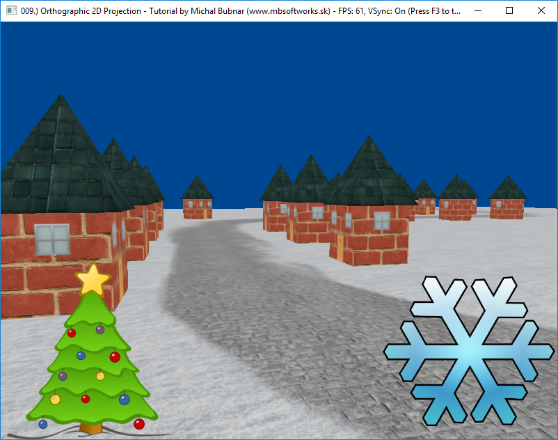
I think it is a really nice thing to know and now you should be able to render some nice gaming panels . But because it's Christmas time (my favorite time of the year), "Christmasy" scene was simply a must. I really hope you have enjoyed this rather short tutorial and see you in the next one! Until then, enjoy your Christmas holiday!
 Download 3.75 MB (1299 downloads)