Welcome to the eighth OpenGL 3.3 tutorial. Here we will examine the basic lighting model and then implement it using shaders. This will increase the scene realism further, because lighting is
everywhere and the world would look too flat without it  .
.
We will examine the basic lighting model, that's relatively easy to implement, and you've probably heard of it. It's the ambient, diffuse and specular contribution to final light. That's all, that's the basic light model. End of tutorial, see you next time  !
!
Just kidding, I'll try to explain these terms, so that it is clear to you what each
of them is. But first, we will look at the light source types in the basic lighting model, and then extract terms ambient, diffuse and specular contribution to final light.
There are three basic light sources in the simplest model - directional light, point light and spotlight. This is how they look like:
Directional light is a light that has a direction, but doesn't have a position, i.e. it's rays are travelling through the scene in a specified direction, but they are not coming from single source. Such light is sun for example - it illuminates everything around, but it's too far from the scene, so its rays are practically parallel and affect every place of scene equally. Depending on the phase of a day, the rays direction from sun change. Its implementation isn't very difficult, and it will be covered in this tutorial.
Point light comes from a single source, like a light bulb. It radiates to all directions, and also has an attenuation - the further object it illuminates, the less light reaches there. This type of light source has a greater computational complexity, but it's still pretty fast and easy to implement, will be in another lighting tutorial.
Spotlight is most difficult from these. It emits a cone of light, with inner cone that has more intense light than outer cone. Only things inside the cone gets illuminated. The most common example is the flashlight. This one is computationally most expensive, and will be implemented later, this is just an introduction to lighting.

Before we proceed, we must learn about normal vectors. Normal vector of a polygon is a vector that is perpendicular to the plane in which polygon lies - forms 90 degrees angle with it. In our case, polygon will always be triangle, because it consists of 3 points and three points, if not colinear, define a plane, whereas 4 points don't have to lie on a same plane neccessary. This vector simply tells us, which direction the polygon is facing. I wrote an article about it very long ago and I edited it when writing this tutorial, so if you are looking for a bit more explanation of normal vectors and vectors generally, and how are they calculated, take a look there right now - click here. So if we have a normal vector and know the direction the triangle is facing, we can start with its illumination. We will implement directional light in this tutorial. So let's get into it.
As I have said in the beginning, directional light has a direction, but it doesn't come from anywhere - in all places of a scene, rays of this light will strike always with same direction. In this tutorial we will implement a sun and you will be able to rotate it around the scene to change its direction with left and right arrow keys (like changing day phase).
The main question now is how much will object be lit by that light? This thing is determined for every single face (triangle) - we will test the directional vector of our light against normal vector of a face. The object will get full light color, when vectors are parallel and face distinct directions, and no light, when vectors form a right angle. And for everything in between, we will deal with cosine of angle between normal vector and direction of light. And as you may know from theory, dot product between two vectors that are normalized is the cosine of angle between - exactly what we need! (If you don't know these relations between vectors and angles and cross products and stuff, check my older articles (click here) to clarify these things). Dot product is also natively supported in GLSL, so there won't be any problem with that. All we need to tell shader is direction and color of our directional light. In order to have everything packed comfortly, GLSL 3.30 (and higher) support struct. So we will create one for directional light, and it will have these parameters: direction, color of light, and ambient intensity. This struct will be uniform and we will set it from program.
#version 330

uniform mat4 projectionMatrix;
uniform mat4 modelViewMatrix;
uniform mat4 normalMatrix;

layout (location = 0) in vec3 inPosition;
layout (location = 1) in vec2 inCoord;
layout (location = 2) in vec3 inNormal;

out vec2 texCoord;

smooth out vec3 vNormal;

void main()
{
	gl_Position = projectionMatrix*modelViewMatrix*vec4(inPosition, 1.0);
	texCoord = inCoord;
	vec4 vRes = normalMatrix*vec4(inNormal, 0.0);
	vNormal = vRes.xyz;
}
And fragment shader:
#version 330

in vec2 texCoord;
smooth in vec3 vNormal;
out vec4 outputColor;

uniform sampler2D gSampler;
uniform vec4 vColor;

struct SimpleDirectionalLight
{
	vec3 vColor;
	vec3 vDirection;
	float fAmbientIntensity;
};

uniform SimpleDirectionalLight sunLight;

void main()
{
	vec4 vTexColor = texture2D(gSampler, texCoord);
	float fDiffuseIntensity = max(0.0, dot(normalize(vNormal), -sunLight.vDirection));
	outputColor = vTexColor*vColor*vec4(sunLight.vColor*(sunLight.fAmbientIntensity+fDiffuseIntensity), 1.0);
}
I mentioned ambient intensity, but didn't explain it. What's that? In real world, if you have a lamp that illuminates dark room, even objects that aren't illuminated directly, but are let's say behind other objects are slightly illuminated. This is because light gets scattered all over the place. Of course, to simulate this would be a horror, but approximating it with simple constant - ambient intensity is enough for this tutorial (I wanted to simulate rays in shaders, but then I took an arrow to the knee  ). It says how much will objects be lit by that light no matter the direction they're facing or their position. In this tutorial I set it to 0.2. So the ambient contribution to final color is ambientLightColor*ambientIntensity.
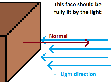
Another type of light contribution to final color is diffuse. This one does depend on direction between normal and light. And that's the variable fDiffuseIntensity in fragment shader - how much additional light will get applied to final color. If normal and light direction are parallel and facing opposite directions, for example normal is (1, 0, 0) and light direction is (-1, 0, 0), then that face should be lit as much with that light as possible. And that's why diffuse intesity is calculated with -vLightDirection - the opposite vector. In our example, dot product return would return -1.0 and this is cosine of angle between these vectors. Converting to actual angle will result in 180.0 degrees. But when facing opposite directions, we want the object to be lit, so that diffuse component should be 1.0 instead. Reverting light direction will alter results of dot product, which will be 1.0 now, and we are good (angle is 0 degrees). Notice, that if angle is between 90 and 180 degrees, diffuse contribution is 0.0, because the dot product returns negative value, and we clamp it to 0.0 with max function, because we don't want to suck out the light from the place, even though we directly don't illuminate it:

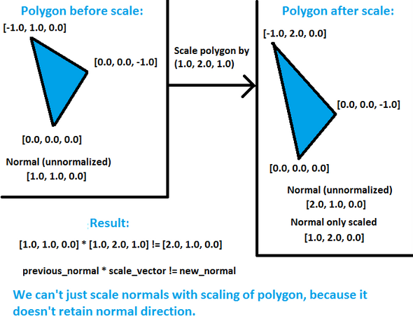
Let's examine these shaders to understand directional lights. Look at the vertex shader. There is a new matrix called normal matrix. What exactly is this? Well, when we transform objects into eye-space coordinates (rotate whole universe  ), we also need to transform normals somehow, so they will face the right direction. We simply need to work in same space with vertex coordinates and normals as well. When using translation, there's no need to change normals - we're just moving our objects around, directions of normals stay the same. When using rotations, we need to rotate normals as well, and when scaling objects, another problem may arise, because it involves changing lengths of normals. In uniform scales (i.e. we scale by the same amount along X, Y and Z axis), this doesn't cause any problems, because it acts like scalar multiplication of vector - we just changed its length, but preserved directions. But in non-uniform scales, the new normal isn't perpendicular - say we scaled the polygon by (1, 2, 1), the new normal won't correspond the polygon. This picture will show more than thousand words:

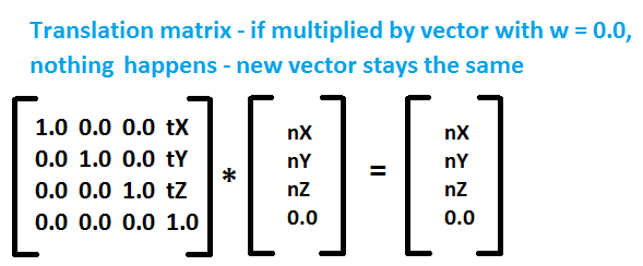
So we must find a way how to transform this normals depending on the previous transformations and we want to find some nice way to do it. It turns out, that the proper way to transform normals is to take transpose of the inverse matrix of transformations performed locally on object. Transpose of matrix is matrix flipped around its diagonal (http://en.wikipedia.org/wiki/Transpose) and inverse matrix of A is such matrix B, that A*B = B*A = I, where I is identity matrix (http://en.wikipedia.org/wiki/Invertible_matrix). Have a look at wikipedia links provided to make sure you understand these terms. So let's say that after we \"looked\" at the scene, i.e. transformed objects to proper positions and rotations in eye-space coordinates, we may need to change normals. But when? Only when we do additional transformations to objects locally, for example if we additionaly rotate toroid or cube in our sample, or scale them. Translation doesn't interest us, because it doesn't affect normal at all (we're just moving around), and even mathematically speaking, normal has a zero w component and if you have a look at translation matrix, you'll notice that the translation factors won't get involved in normal calculations:

So all we need to do is to find inverse of transpose matrix of local transformations to transform normals properly. Additional question may arise in your head: Why not taking whole modelview matrix? Answer to that is - it won't work (you can try it to see what will happen - object will be lit depending on your position and direction you're looking). It's because when I'm looking in any direction (calling the look function), the normals stay the same in world coordinates . If I have a pure, unrotated cube and it's right-side normal is (1, 0, 0), no matter where I look this normal will be (1, 0, 0) and lighting calculations must be done with these values. The other case is If I rotate cube by 90 degrees on Y axis clockwise. The formerly right side of the cube is now in the front, facing direction (0, 0, 1) towards us, and calculations of lighting are done with this. Think of it a while and eventually you'll understand. Once you do, you are on a very good way on understanding lighting and things involved around it.
The most important thing - why do we take inverse of transpose of matrix and it works? The knowledge is taken from matrix algebra, and it's hard to explain in few sentences. So I will just give you a good source where you can discover more, and maybe once I'll write article about matrices, because it's a whole great topic (we had whole term at university with matrix algebra). Look around internet for other lighting tutorials, in some of them these matrices stuff is explained a little more. Here is one link for this kind of informations: http://tog.acm.org/resources/RTNews/html/rtnews1a.html#art4.
Now that we know that we must take inverse of transpose matrix, glm provides functions for doing so. We calculate these things on CPU and pass them to shaders as uniform variables. Even though GLSL has functions to calculate inverse and transpose of matrix, we won't do that, because we need to calculate it only once before rendering, and not per vertex. Another thing is that after we transformed normal properly, it has a smooth modifier. This means the same thing as in tutorial with shaders and colors - normal gets interpolated along all pixels. So we achieved per-pixel lighting almost for free  (except for more computational power)! But then we must normalize it in fragment shader, because length of that normal probably won't be of unit length, and for proper calculations it must be. You can also modify color of objects in this shader (uniform vec3 vColor).
Important change is also in rendering function - I added function setUniform to CShaderProgram class to make setting uniforms more comfortable. We weren't talking about specular contribution to final color - this one is responsible for those shiny reflections on objects. It will be in another lighting tutorial, that won't be that far from this one. I also added new .cpp file called static_geometry.cpp, that involves a torus calculation function. You can have a look at it, it's not that hard to calculate torus, but it's not crucially important to understand it - just know it works  .
.
Even though this is a very simple lighting model, that doesn't involve material properties, results of it are actually pretty:

I hope that after reading this tutorial you have a better understanding of how lighting works. Of course, these are very basics, but procedurally we will build more advanced lighting system, that will come in later tutorials. You may rest from lighting for a while, next tutorial will bring orthographic projection and font rendering in OpenGL using FreeType library.
 Download 1.43 MB (7870 downloads)